
Web 图形与 3D / 系统课时
叠加法线贴图改变光照细节
叠加法线贴图改变光照细节
这节课让一块没有几何起伏的平面呈现细密的受光变化。我们会把纹理 RGB 还原成切线空间法线,再借助 TBN 基底把它转换到世界空间,并通过左右对照确认:网格轮廓不变,光照明暗发生变化。
学习目标
- 解释法线贴图的 RGB 编码、线性采样及归一化规则。
- 根据顶点法线、切线和手性符号构造 TBN 并转换法线。
- 运行 WebGPU 示例,对比普通漫反射与法线贴图效果,并排查方向错误。
将纹理颜色还原为法线
颜色贴图记录表面颜色,切线空间法线贴图则用 RGB 存储 XYZ 方向。采样值位于 0~1,需按 sampled.rgb * 2.0 - 1.0 解码。近似平坦的像素 RGB(128, 128, 255) 会还原为接近 (0, 0, 1) 的向量,表示法线沿表面外侧方向。
法线贴图是向量数据,GPUTexture 使用 rgba8unorm,不要使用 rgba8unorm-srgb 对向量分量做颜色空间转换。线性过滤后必须再次 normalize,否则插值会改变向量长度。法线贴图只修改照明计算的方向,不修改顶点、轮廓或真实的遮挡关系。
用 TBN 对齐贴图与光源空间
T 是 UV 的 U 增长方向,B 是 V 增长方向,N 是几何法线。三者组成切线空间到世界空间的基底:贴图法线 nTS 变为 normalize(T * nTS.x + B * nTS.y + N * nTS.z),然后才能与世界空间方向光计算点积。
本例平面位于 XY 平面,T=(1,0,0)、B=(0,1,0)、N=(0,0,1)。顶点切线使用 vec4f,其中 w=1 表示基底手性;片元中先将 T 对 N 正交化,再用 cross(N,T) * tangent.w 恢复 B。镜像 UV 岛可能需要 w=-1,不能固定所有网格为正号。
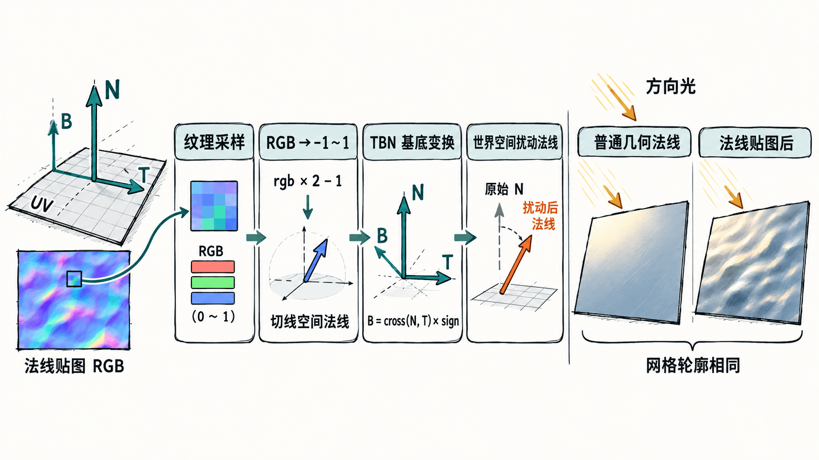
真实模型的 T 应来自与法线贴图烘焙一致的切线定义,例如模型文件的 glTF TANGENT 属性;光源和转换后的法线必须位于同一空间。存在非等比缩放时,N 需通过模型矩阵左上角 3×3 的逆转置法线矩阵变换,T 经模型矩阵变换后再正交化。
运行平面受光对照示例
下面的单文件示例自行生成 128×128 法线贴图,省去图片下载和路径问题。它用两个三角形拼成平面,左半部分始终使用几何法线,右半部分使用贴图法线;两侧共用光照方向和颜色,差异只来自法线。
将代码保存为 index.html,在该文件所在目录执行 python3 -m http.server 8000,然后使用支持 WebGPU 的浏览器访问 http://localhost:8000/。WebGPU 需要安全上下文;本机 localhost 可用于开发。
<!doctype html>
<html lang="zh-CN">
<meta charset="utf-8">
<title>WebGPU 法线贴图对照</title>
<style>
  body { font: 16px sans-serif; margin: 24px; }
  canvas { display: block; max-width: 100%; }
</style>
<canvas id="view" width="800" height="480"></canvas>
<p>左:几何法线(平面) 右:切线空间法线贴图(凹凸受光)</p>
<script type="module">
const canvas = document.querySelector("#view");
if (!navigator.gpu) throw new Error("浏览器未启用 WebGPU");
const adapter = await navigator.gpu.requestAdapter();
if (!adapter) throw new Error("找不到兼容的 GPU 适配器");
const device = await adapter.requestDevice();
const context = canvas.getContext("webgpu");
const format = navigator.gpu.getPreferredCanvasFormat();
context.configure({ device, format, alphaMode: "opaque" });

// 单个顶点:位置 3 + UV 2 + 法线 3 + 切线 4,共 48 字节。
const corners = [
  [-0.9, -0.9, 0, 0, 0], [0.9, -0.9, 0, 1, 0],
  [ 0.9,  0.9, 0, 1, 1], [-0.9, 0.9, 0, 0, 1]
];
const vertices = new Float32Array(
  [0, 1, 2, 0, 2, 3].flatMap(i => [
    ...corners[i], 0, 0, 1, 1, 0, 0, 1
  ])
);
const vertexBuffer = device.createBuffer({
  size: vertices.byteLength,
  usage: GPUBufferUsage.VERTEX | GPUBufferUsage.COPY_DST
});
device.queue.writeBuffer(vertexBuffer, 0, vertices);

// 根据周期性高度场的斜率,生成编码在 RGB 中的切线空间法线。
const size = 128;
const pixels = new Uint8Array(size * size * 4);
for (let y = 0; y < size; y++) {
  for (let x = 0; x < size; x++) {
    const u = (x + 0.5) / size, v = (y + 0.5) / size;
    const a = u * Math.PI * 12, b = v * Math.PI * 12;
    const gx = 0.7 * Math.cos(a) * Math.sin(b);
    const gy = 0.7 * Math.sin(a) * Math.cos(b);
    const length = Math.hypot(gx, gy, 1);
    const normal = [-gx / length, -gy / length, 1 / length];
    const offset = (y * size + x) * 4;
    for (let c = 0; c < 3; c++) {
      pixels[offset + c] = Math.round((normal[c] * 0.5 + 0.5) * 255);
    }
    pixels[offset + 3] = 255;
  }
}
const normalTexture = device.createTexture({
  size: [size, size],
  format: "rgba8unorm",
  usage: GPUTextureUsage.TEXTURE_BINDING | GPUTextureUsage.COPY_DST
});
device.queue.writeTexture(
  { texture: normalTexture }, pixels,
  { bytesPerRow: size * 4 }, [size, size]
);
const sampler = device.createSampler({
  magFilter: "linear", minFilter: "linear",
  addressModeU: "repeat", addressModeV: "repeat"
});

const shader = device.createShaderModule({ code: `
struct Varyings {
  @builtin(position) position: vec4f,
  @location(0) uv: vec2f,
  @location(1) worldNormal: vec3f,
  @location(2) worldTangent: vec4f,
}
@vertex fn vs_main(
  @location(0) pos: vec3f,
  @location(1) uv: vec2f,
  @location(2) n: vec3f,
  @location(3) t: vec4f
) -> Varyings {
  var out: Varyings;
  out.position = vec4f(pos, 1.0);
  out.uv = uv;
  out.worldNormal = n;
  out.worldTangent = t;
  return out;
}
@group(0) @binding(0) var normalMap: texture_2d<f32>;
@group(0) @binding(1) var normalSampler: sampler;
@fragment fn fs_main(input: Varyings) -> @location(0) vec4f {
  let N = normalize(input.worldNormal);
  let T = normalize(input.worldTangent.xyz -
                    dot(input.worldTangent.xyz, N) * N);
  let B = cross(N, T) * input.worldTangent.w;
  // 纹理是线性向量数据;插值后重新单位化。
  let nTS = textureSample(normalMap, normalSampler, input.uv).xyz
            * 2.0 - vec3f(1.0);
  let mappedN = normalize(T * nTS.x + B * nTS.y + N * nTS.z);
  let pickedN = select(N, mappedN, input.uv.x >= 0.5);
  let L = normalize(vec3f(0.4, 0.5, 1.0));
  let diffuse = max(dot(pickedN, L), 0.0);
  let color = vec3f(0.26, 0.70, 0.75) * (0.22 + 0.78 * diffuse);
  return vec4f(color, 1.0);
}
` });
const pipeline = device.createRenderPipeline({
  layout: "auto",
  vertex: {
    module: shader, entryPoint: "vs_main",
    buffers: [{
      arrayStride: 48,
      attributes: [
        { shaderLocation: 0, offset: 0, format: "float32x3" },
        { shaderLocation: 1, offset: 12, format: "float32x2" },
        { shaderLocation: 2, offset: 20, format: "float32x3" },
        { shaderLocation: 3, offset: 32, format: "float32x4" }
      ]
    }]
  },
  fragment: {
    module: shader, entryPoint: "fs_main", targets: [{ format }]
  },
  primitive: { topology: "triangle-list" }
});
const bindGroup = device.createBindGroup({
  layout: pipeline.getBindGroupLayout(0),
  entries: [
    { binding: 0, resource: normalTexture.createView() },
    { binding: 1, resource: sampler }
  ]
});

// 只绘制一次;左右对照由片元着色器决定。
const encoder = device.createCommandEncoder();
const pass = encoder.beginRenderPass({
  colorAttachments: [{
    view: context.getCurrentTexture().createView(),
    loadOp: "clear", storeOp: "store",
    clearValue: { r: 0.98, g: 0.99, b: 1, a: 1 }
  }]
});
pass.setPipeline(pipeline);
pass.setBindGroup(0, bindGroup);
pass.setVertexBuffer(0, vertexBuffer);
pass.draw(6);
pass.end();
device.queue.submit([encoder.finish()]);
</script>
</html>
预期结果:页面出现一块青绿色矩形,左半侧亮度近乎均匀,右半侧有周期性的明暗起伏;中间的分界清楚,但两侧几何边缘保持笔直。终端提供静态文件服务,不需要外部图片或着色器文件。
定位方向与材质错误
如果整块平面受光均匀,先确认 textureSample 返回的值不是恒定 (0.5,0.5,1.0),再检查片元是否真的使用 mappedN。可以把 pickedN 暂时全部改成 mappedN:正确结果是整块平面都有纹理造成的起伏明暗。
如果凹槽看起来向外鼓,检查法线贴图绿色通道约定。有的素材以 +Y 表示切线空间向上,有的以 -Y 表示向下;当贴图与引擎约定不同时,可尝试只翻转解码后法线的 y 分量,并与原素材预期方向核对,不能随意翻转世界坐标的 Y 轴。
当模型发生镜像 UV 或非等比缩放时,优先检查 tangent.w、T 的正交化以及 N 的逆转置变换。使用法线贴图不会增加凹凸轮廓:需要真实剪影或遮挡变化时,应改用几何位移、视差映射等专门方法。