
Web 图形与 3D / 系统课时
用法线计算方向光漫反射
用法线计算方向光漫反射
让三维模型的不同朝向呈现自然的明暗变化,需要把顶点法线和方向光放在同一坐标空间,再按 Lambert 规则计算亮度。这里用 WebGPU 绘制一个经过旋转、非等比缩放的椭球,实际验证光照方向和法线矩阵的作用。
学习目标
- 根据法线与光方向的夹角计算漫反射系数。
- 使用逆转置法线矩阵处理非等比缩放后的模型。
- 运行 WGSL 示例,并通过调整光方向检验明暗变化。
理解 Lambert 计算与方向约定
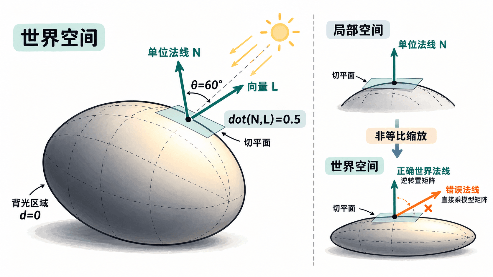
每个顶点提供局部空间法线。模型经过变换后,先把法线转换到世界空间,再与同样定义在世界空间的方向光比较。这里的光向量 特指从表面指向光源的方向,不是光线传播方向。
设单位世界法线为 ,Lambert 漫反射系数为:
正对光源时 ;夹角为 60° 时 ;背向光源时 。示例为避免背光侧完全不可见,额外使用 0.18 的常量环境项,最终颜色系数为 。这项环境补光不属于 Lambert 漫反射本身。
用 WGSL 实现世界空间光照
保存下方完整内容为 index.html,在文件所在目录运行 python3 -m http.server 8000,再用支持 WebGPU 的浏览器打开 http://localhost:8000。localhost 是可信本地来源;普通非 HTTPS 远程页面可能无法使用 WebGPU。
代码采用 24×48 段球面三角形。顶点格式为位置 3 个 f32 加法线 3 个 f32,每顶点 24 字节。模型沿 X 轴放大 1.45 倍、沿 Z 轴缩小到 0.65 倍;法线使用对应的逆转置变换,并在片元阶段重新归一化。
<!doctype html>
<html lang="zh-CN">
<meta charset="utf-8">
<title>WebGPU Lambert 漫反射</title>
<body style="margin:24px;font:16px system-ui;background:#f3f6f8">
<canvas id="view" width="800" height="500" style="max-width:100%"></canvas>
<p id="status">正在初始化</p>
<script type="module">
async function main() {
  if (!navigator.gpu) throw new Error("当前浏览器或上下文不支持 WebGPU");
  const adapter = await navigator.gpu.requestAdapter();
  if (!adapter) throw new Error("未找到可用的 GPU 适配器");
  const device = await adapter.requestDevice();
  const canvas = document.querySelector("#view");
  const context = canvas.getContext("webgpu");
  const format = navigator.gpu.getPreferredCanvasFormat();
  context.configure({ device, format, alphaMode: "opaque" });

  const wgsl = `
struct Uniforms {
  model: mat4x4f,
  viewProj: mat4x4f,
  normalMatrix: mat4x4f,
  lightDir: vec4f,
  albedo: vec4f,
};
struct VertexIn {
  @location(0) position: vec3f,
  @location(1) normal: vec3f,
};
struct VertexOut {
  @builtin(position) clipPosition: vec4f,
  @location(0) worldNormal: vec3f,
};
@group(0) @binding(0) var<uniform> u: Uniforms;

@vertex fn vs(input: VertexIn) -> VertexOut {
  var output: VertexOut;
  let worldPosition = u.model * vec4f(input.position, 1.0);
  output.clipPosition = u.viewProj * worldPosition;
  output.worldNormal = (u.normalMatrix * vec4f(input.normal, 0.0)).xyz;
  return output;
}
@fragment fn fs(input: VertexOut) -> @location(0) vec4f {
  let N = normalize(input.worldNormal);
  let L = normalize(u.lightDir.xyz);
  let diffuse = max(dot(N, L), 0.0);
  let brightness = 0.18 + 0.82 * diffuse;
  return vec4f(u.albedo.rgb * brightness, 1.0);
}`;
  const module = device.createShaderModule({ code: wgsl });

  // 球面法线等于单位球面顶点位置,顶点数据按位置/法线交错排列。
  const data = [];
  const point = (t, p) => [
    Math.sin(t) * Math.cos(p), Math.cos(t),
    Math.sin(t) * Math.sin(p)
  ];
  const emit = v => data.push(...v, ...v);
  for (let i = 0; i < 24; i++) {
    for (let j = 0; j < 48; j++) {
      const t0 = Math.PI * i / 24, t1 = Math.PI * (i + 1) / 24;
      const p0 = Math.PI * 2 * j / 48, p1 = Math.PI * 2 * (j + 1) / 48;
      const a = point(t0, p0), b = point(t1, p0);
      const c = point(t0, p1), d = point(t1, p1);
      for (const v of [a, b, c, c, b, d]) emit(v);
    }
  }
  const vertices = new Float32Array(data);
  const vertexBuffer = device.createBuffer({
    size: vertices.byteLength,
    usage: GPUBufferUsage.VERTEX | GPUBufferUsage.COPY_DST
  });
  device.queue.writeBuffer(vertexBuffer, 0, vertices);

  const a = Math.PI / 6, c = Math.cos(a), s = Math.sin(a);
  const sx = 1.45, sy = 1.0, sz = 0.65;
  // 对于 R*S,法线矩阵是 R*inverse(S),不是直接复用模型矩阵。
  const model = [
    c*sx, 0, -s*sx, 0,  0, sy, 0, 0,
    s*sz, 0, c*sz, 0,  0, 0, 0, 1
  ];
  const normalMatrix = [
    c/sx, 0, -s/sx, 0,  0, 1/sy, 0, 0,
    s/sz, 0, c/sz, 0,  0, 0, 0, 1
  ];
  // 固定正交投影:裁剪空间的 Z 值保持在 WebGPU 的 [0,1]。
  const viewProj = [
    0.55, 0, 0, 0,  0, 0.8, 0, 0,
    0, 0, 0.22, 0,  0, 0, 0.5, 1
  ];
  const uniforms = new Float32Array([
    ...model, ...viewProj, ...normalMatrix,
    -0.55, 0.75, -0.7, 0,  0.13, 0.72, 0.64, 1
  ]);
  const uniformBuffer = device.createBuffer({
    size: uniforms.byteLength,
    usage: GPUBufferUsage.UNIFORM | GPUBufferUsage.COPY_DST
  });
  device.queue.writeBuffer(uniformBuffer, 0, uniforms);

  const pipeline = device.createRenderPipeline({
    layout: "auto",
    vertex: {
      module, entryPoint: "vs",
      buffers: [{
        arrayStride: 24,
        attributes: [
          { shaderLocation: 0, offset: 0, format: "float32x3" },
          { shaderLocation: 1, offset: 12, format: "float32x3" }
        ]
      }]
    },
    fragment: { module, entryPoint: "fs", targets: [{ format }] },
    primitive: { topology: "triangle-list" },
    depthStencil: {
      format: "depth24plus", depthWriteEnabled: true, depthCompare: "less"
    }
  });
  const bindGroup = device.createBindGroup({
    layout: pipeline.getBindGroupLayout(0),
    entries: [{ binding: 0, resource: { buffer: uniformBuffer } }]
  });
  const depth = device.createTexture({
    size: [canvas.width, canvas.height],
    format: "depth24plus",
    usage: GPUTextureUsage.RENDER_ATTACHMENT
  });
  const encoder = device.createCommandEncoder();
  const pass = encoder.beginRenderPass({
    colorAttachments: [{
      view: context.getCurrentTexture().createView(),
      clearValue: { r: 0.04, g: 0.06, b: 0.09, a: 1 },
      loadOp: "clear", storeOp: "store"
    }],
    depthStencilAttachment: {
      view: depth.createView(),
      depthClearValue: 1, depthLoadOp: "clear", depthStoreOp: "store"
    }
  });
  pass.setPipeline(pipeline);
  pass.setBindGroup(0, bindGroup);
  pass.setVertexBuffer(0, vertexBuffer);
  pass.draw(vertices.length / 6);
  pass.end();
  device.queue.submit([encoder.finish()]);
  document.querySelector("#status").textContent = "已提交绘制命令";
}
main().catch(error => {
  document.querySelector("#status").textContent = error.message;
  console.error(error);
});
</script>
</body>
</html>
预期结果:画布中央出现青绿色、横向略拉伸的椭球,朝向光源的左上侧更亮,背光侧更暗但不全黑;画布下方显示“已提交绘制命令”。这是一帧静态渲染,不需要动画循环。
修改参数并验证法线是否正确
- 将
uniforms中的方向光四个分量改为0, 0, -1, 0,刷新后朝向观察者的表面更亮;改为0, 0, 1, 0,可见正面大部分转暗。这可以确认L的方向约定。 - 保留
sx=1.45、sz=0.65,暂时将...normalMatrix替换为...model。虽然轮廓不变,但高亮区域会偏移;恢复逆转置矩阵后,照明才与椭球的真实表面朝向匹配。 - 把
sx与sz都改为1.0,并刷新。轮廓接近球形;法线矩阵此时与纯旋转矩阵相同,因此错误做法暂时不容易暴露。
如果页面完全空白,先检查浏览器是否支持 WebGPU、是否从 localhost 或 HTTPS 打开,再看开发者工具控制台的着色器或管线校验错误。若模型能显示但亮暗反向,应检查传入的是“指向光源”还是“光线传播”向量;若缩放后明暗异常,应核对矩阵列主序、逆转置以及片元中的 normalize。